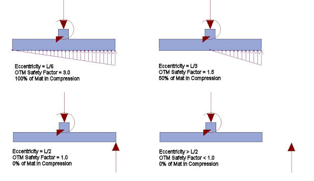
One of the important results from any footing analysis is a ratio of the stabilizing moments to the de-stabilizing moments. This is referred to as the Stability Ratio or the Safety Factor for overturning. RISAFoot calculates this value differently than the way many engineers would traditionally approach a hand calculation. The RISA method is a bit more complicated, but will provide a more realistic representation of the true safety factor versus overturning whenever uplift loads are present. A comparison of the two methods is provided below.
The overturning safety factor (OSF) is the sum of resisting moments divided by the sum of overturning moments. Most codes require that this factor be greater than 1.5. Overturning safety factor calculations are based on the service load combinations only and are calculated in both the X and Z directions.
Most hand calculations are done on the assumption that all vertical loads are stabilizing loads that are only capable of producing a stabilizing moment whereas all lateral shear and moments will act to de-stabilize the structure. As an example consider the case where you have the following Loads applied to a 4x4 footing with a pedestal that extends 2 ft above the bottom of the footing.
| Force Effect | Dead Load | Wind Load |
|---|---|---|
| Axial | 25 kips | +/- 10 kips |
| Shear | 0 | 5 kips |
In the traditional method, the axial forces are combined together to form a total vertical load. Since the TOTAL EFFECT of the axial loads is considered a stabilizing effect the resisting moment is considered to be P*L/2. Since the only de-stabilizing effect is assumed to be the shear force the de-stabilizing moment would be calculated as V*H. These calculations are summarized in the table below.
|
Wind Effect |
Stabilizing Moment |
DeStabilizing Moment |
OTM Safety Factor |
|---|---|---|---|
| Downward | 70 k-ft | 10 k-ft | 7.0 |
| Uplift | 30 k-ft | 10 k-ft | 3.0 |
The True Safety Factor method used by RISAFoot involves taking a look at EVERY component of every load and deciding whether it has a stabilizing or a de-stabilizing effect. Overturning moments are those applied moments, shears, and uplift forces that seek to cause the footing to become unstable and turn over. Resisting moments are those moments that resist overturning and seek to stabilize the footing. These overturning checks are performed for overturning about each edge of the footing. This is important for footings with eccentric pedestals where the vertical loads will have different stabilizing effects for each face.
By summing up all the resisting moments and comparing them to the sum of all the overturning moments we get a better sense of the true tendency of the structure to overturn. Taking the example listed above, it is clear that when the wind forces act in compression, the two method will produce identical results. That means that if the Wind shear is increased by a factor of 7.0, then the footing would be in net overturning.
However, the stabilizing moment in the uplift case would be viewed as the FULL dead load * L/2 rather than the reduced axial load used in the traditional method. Similarly, the de-stabilizing load would be viewed as the sum of the moments about the edge of the footing. This includes the de-stabilizing effect of the wind uplift and is equal to P_wind* L/2 + V*H.
The OTM Safety Factor calculations for the True Safety Factor Method are summarized in the table below:
|
Wind Effect |
Stabilizing Moment |
DeStabilizing Moment |
OTM Safety Factor |
|---|---|---|---|
| Downward | 70 k-ft | 10 k-ft | 7.0 |
| Uplift | 50 k-ft | 30 k-ft | 1.67 |
Which is a more accurate representation of the safety factor of stability ratio for the uplift case? The best way to judge this is to multiple the wind load by a factor equal to the Safety factor and to see if the footing still works. If the wind effects (shear and uplift) are multiplied by a factor of 3.0 as given by the traditional method, then the footing will be unstable due to net uplift and net overturning. The Safety Factor would be calculated a negative value which has little physical meaning. If the wind effects (shear and uplift) are multiplied by a factor of 1.67 as given by the True Safety Factor method, then the stabilizing moment will equal the de-stabilizing moment and the safety factor becomes 1.0 as predicted.
Older versions of the program could not handle situations where the Ultimate Level load combinations resulted in net overturning of the Footing. This is because the previous versions always relied on the soil bearing pressure calculations to derive the moment and shear demand in the footing. For net overturning cases, the current version of the program assumes that the design shear and moment can be based on the total vertical load and the net eccentricity of that load.

In these cases, where the resultant is off the footing, the design shear force in the footing will be constant equal to the net resultant minus any effects of self weight or over burden. Also, the basis for the design moment at the face of the pedestal will be the load resultant times the distance from the resultant to the face of the pedestal. Any negative moment effect due to the self weight of the footing slab and overburden would be subtracted out when determining the final design moment.